¶ Shut In Tubing Leak
Shut-In Tubing Leak load case can be assigned for:
- Production string (casing, liner, tieback)
- Production tubing

¶ Shut-In Tubing Leak for production string
This is a post installation production burst load case.
- Internal pressure assumes shut-in tubing pressure on the packer fluid hydrostatic in the tubing annulus to the packer and tubing internal pressure below the packer.
- Shut-in tubing pressure (at the top of the tubing, or at the top of the production casing or tieback or at the mudline or at the surface for onshore wells) SITP = p@ perf − Cρprod(zperf−ztt)
- From the top of the casing (or tieback) to the packer depth pi(z) = SITP + Cρpacker(z−ztt)
For a well with a production casing and a production liner, internal pressure for the production casing is calculated from the top of the casing to the top of the liner. Then the pressure in the section below the top of liner to the
production casing shoe is calculated using Blade external pressure protocol for the liner burst load (see at the end of this section for detail).
Following is the summary of the external pressure for the liner burst load -
The external pressure profile for burst load on the liner is same for both drilling and production load cases. Calculations are performed from bottom-up method with the pressure be lost to the formation starting from the TOC if the TOC is deeper than the prior shoe otherwise from the prior string shoe. First, pressure at the TOC is calculated assuming the pressure be lost to formation at max(zTOC,zps). Next, the pressures above zTOC up to the top of the liner are calculated using original MW and finally the pressures below the TOC to the bottom of the liner are calculated using original MW in the cemented pipe-in-pipe section and pore pressure in the cemented open hole section.
- From packer to perforation depth pi(z) = p@ perf − Cρprod(zperf−z)
- From perforation depth to the shoe depth pi(z) = p@ perf + Cρprod(z−zperf)
where,
- pi(z) = internal pressure at the depth of interest, psi.
- p@ perf = pore pressure at the perforation depth, psi. Pore pressure at the perforation depth is obtained from the given pore pressure profile and that will be defaulted to the standard load.
- SITP = shut-in tubing pressure, psi
- z = true vertical depth of interest, ft
- zperf = true vertical depth of the perforation, ft
- ztt = true vertical depth of the top of the tubing, ft
- ρpacker = packer fluid density (fluid outside production tubing), ppg
- ρprod = production fluid density, ppg
- The external pressure of the production burst load for production casing, tieback and liner are discussed at the end of this section.
An alternative external pressure profile is also commonly used for this load which is ’mud-base fluid density above TOC, cement mix-fluid density below TOC inside the prior string (cement in pipe-in-pipe section) and pore pressure in the open hole’.
- Pressure from the top of the string to the TOC pe(z) = Cρmmz
- Pressure at TOC is assumed as the pressure loss to surface with mud-base fluid density pe(zTOC) = CρmmzTOC
- Pressure in the cemented pipe-in-pipe section pe(z) = pe(zTOC) + Cρcm(z−zTOC)
- Pressure in the cemented open hole below the TOC pe(z) = ppp(z)
where,
- pe(z) = external pressure at the depth of interest, psi.
- ptt = pressure at the top of the tubing, psi. Top of the tubing, top of the production casing or tieback and mudline are assumed to be at the same depth for offshore wells. For onshore wells, this will be equal to surface.
- ppp(z) = pore pressure at the depth of interest, psi
- ρmm = mud-mix fluid density, ppg. Default mud mix fluid density is assumed as 8.33 ppg for water based mud and as 7.0 ppg for oil and synthetic based mud.
- ρcm = cement-mix fluid density, ppg. Default mud mix fluid density is assumed as 8.33 ppg.
- Production temperature for the hot shut-in tubing leak and undisturbed temperature for the cold shut-in tubing leak load can be assumed. The default selection of the temperature for this load case is undisturbed.
¶ Shut-In Tubing Leak Load for production casing and production tieback
Shut-In Tubing Leak load is for production casing and production tieback. Production liner is discussed in the next section.
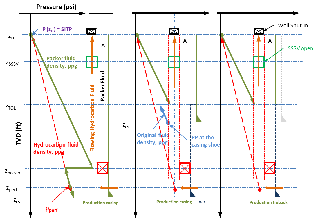
The Green line is the internal pressure profile for the production casing. For production casing configuration (no production liner), the internal pressure will be calculated with SITP on packer fluid to the packer depth and below the packer, it is calculated with pore pressure at the perforation depth minus hydrocarbon fluid hydrostatic pressure.
For the production casing – liner configuration, the internal pressure for the casing covered by the liner is shown with a Blue line. This pressure profile is calculated according to Blade’s external pressure protocol, which is -
- Pore pressure at the production casing shoe
- Cement-mix fluid density to the top of the cement (TOC) of the liner (if TOC is shallower than production casing shoe) the and then original mud density from the TOC to the top of the liner.
Although the pressure outside the liner can be calculated using couple of alternative methods, the default is set with Blade’s protocol.
For the case of production tieback, there will be no blue line because the production tieback stops at the top of the production liner and the packer is much deeper than the bottom of the production tieback.
The Red line is the internal pressure profile for the production tubing which is same as the internal pressure profile of the shut-in tubing load case. The SITP is calculated using this profile at the top of the tubing.

- The internal pressure at the top of the production casing or production tieback is equal to the SITP which is calculated as SITP = p@ perf − Cρprod(zperf−ztt)
- The internal pressure from the top of the casing or tieback to the end of the tieback or at the top of the production liner will be pi(z) = SITP + Cρpacker(z−ztt)
- The above equation is valid for the production casing (only) configuration up to production packer. Below the production packer the internal pressure for the production casing will be calculated as pi(z) = p@ perf − Cρprod(zperf−z)
- For the production casing - production liner configuration, the pressure below the production liner top to the production casing shoe is calculated as following:
- when liner TOC is deeper than the casing shoe pi(z) = ppp(zcs) − Cρm(zcs−zTOL)
- when liner TOC is shallower than the casing shoe, then -
- pressure at the casing shoe - pi(zcs) = ppp(zcs)
- pressure at the liner TOC - pi(zTOC lnr) = ppp(zcs) − Cρcb(zcs−zTOC lnr)
- pressure above the liner TOC to the liner TOL - pi(zTOL) = pi(zTOC lnr) − Cρm(zTOC lnr−zTOL)
where,
- ρm = original mud weight, ppg
- ρcb = cement-mix fluid density, ppg. Defaulted to 8.33 ppg.
- zcs = true vertical depth of the current (casing) shoe, ft
- zTOC lnr = true vertical depth of the liner TOC, ft
- zTOL = true vertical depth of the liner top, ft
- ppp(zcs) = pore pressure at the casing shoe
¶ Shut-In Tubing Leak Load for production liner
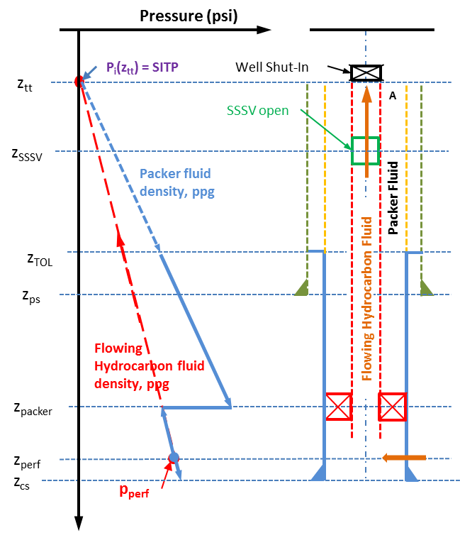
The solid Blue line is the internal pressure profile for the production liner from the top of the liner to the packer depth. The solid red line is for the section of the liner from the packer to the bottom.
The internal pressure at the top of the liner will be – pi(zTOL) = SITP + Cρpacker(zTOL−ztt)
The internal pressure from the top of the liner to the packer will be – pi(z) = pi(zTOL) + Cρpacker(zpacker−zTOL)
The internal pressure below the production packer will be calculated from the perforation depth with the hydrocarbon fluid density as following pi(z) = p@ perf − Cρprod(zperf−z) This will also cover the section from the perforation depth to the liner shoe.

Description of the nomenclatures for Shut-In Tubing Leak Load for production liner image
- zTOL = true vertical depth of the top of the liner, ft
- zps = true vertical depth of the prior string shoe, ft
- zcs = true vertical depth of the liner (current) shoe, ft
¶ Shut-In Tubing Leak for Production tubing
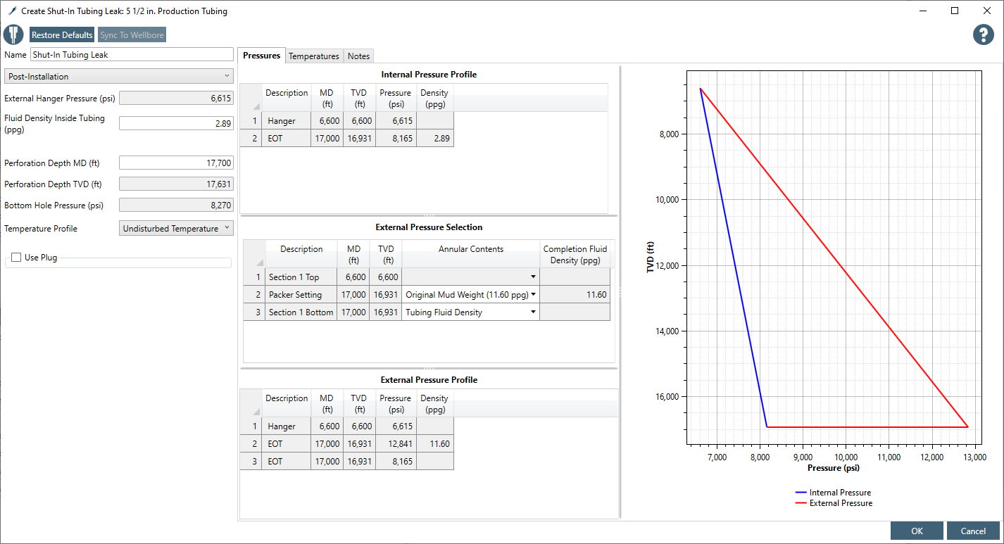
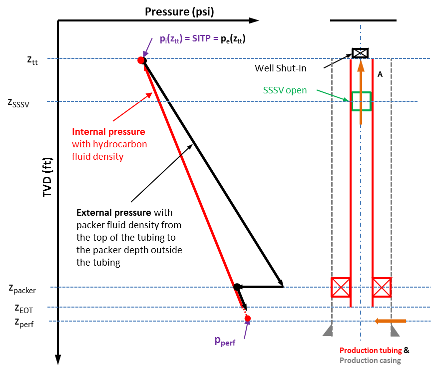
This is a production collapse load case for the production tubing. Internal and external pressure profiles for this load case.
Internal pressure is calculated as pore pressure at the perforation depth minus the flowing hydrocarbon fluid gradient to the top of the tubing. The pressure at the top of the tubing is defined as SITP.
External pressure is calculated starting from the SITP at the top of the tubing and then packer fluid hydrostatic to the packer. External and internal pressures below the packer are equal.

SITP = p@ perf − Cρprod(zperf−ztt) pi(z) = SITP + Cρprod(z−ztt) External pressure from the top of the tubing to packer pe(z) = SITP + Cρpacker(z−ztt) External pressure from the packer to end of tubing - pe(z) = p@ perf − Cρprod(zperf−z)
¶ External pressure profile
The external pressure profile for the burst load on the full string:
- Seawater gradient at the top of the string (hanger) for offshore subsea wells otherwise zero psi for other well configurations,
- Original mud density above TOC, cement mix-fluid density below TOC inside the prior string (cement in pipe-in-pipe section) and pore pressure in the open hole.
The external pressure profile for the burst load on the liner:
- Pressure at TOC
- is equal to the pore pressure at that depth if the TOC is deeper than the prior string shoe, otherwise
- is equal to the pore pressure at the prior string shoe minus fluid hydrostatic with original mud from the prior shoe to the liner TOC
- Original mud density above TOC, original mud density below TOC inside the prior string (cement in pipe-in-pipe section) and pore pressure in the open hole.
There are two differences in the external pressure profiles between drilling and production burst loads as we have discussed in the earlier two sections. They are:
- Pressure at zTOC
- Drilling - Trapped hydrostatic
- Production - Loss to surface
- Fluid density above zTOC
- Drilling - Original mud density
- Production - Mud base fluid density
¶ Temperature profile
Undisturbed temperature profile is assumed as default. Drilling circulating temperature could also be an option to select.