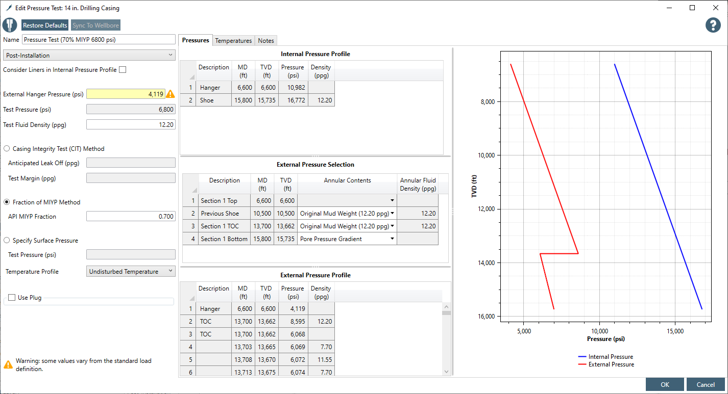
¶ Pressure Test
Pressure test is required for all strings except for the driven pipe. It is a post installation drilling burst load. The internal and external pressure profiles are assumed as following –
- Internal pressure assumes test pressure on the run-in fluid density. The test pressure can be estimated by selecting one of the four following methods -
- Fraction of MIYP Method
- Casing Integrity Test (CIT) Method
- Production Liner Pressure (BSEE) and
- Specify Surface Pressure
Internal pressure profile is constructed with the test pressure on top the internal (test) fluid hydrostatic pi(z) = ptest + Cρiz where,
- ptest = test pressure at the surface, psi
- pi(z) = internal pressure at the depth of interest, psi
- ρi = test fluid density, ppg
- z = true vertical depth of the interest, ft
- C = constant, 0.051948 psi/(ppg×ft)
- External pressure assumes mud-mix fluid density to TOC, cement-mix fluid density below TOC to previous shoe if TOC is above previous shoe, pore pressure below TOC in open hole. The summary of the external pressure profile for the burst load for various string types are following -
- For Casing, Tieback and Tubing
- seawater gradient at the top of the string (hanger) for offshore subsea wells otherwise zero psi for other well configurations,
- trapped hydrostatic with original mud at the TOC (or packer in case of production tubing),
- original mud density above TOC (or packer in case of production tubing), cement mix-fluid density below TOC inside the prior string (cement in pipe-in-pipe section) and pore pressure in the open hole.
- For Liner
- Calculations are performed from bottom-up method with the pressure be lost to formation starting from TOC if TOC is deeper than the prior shoe otherwise from the prior string shoe. First, pressure at TOC is calculated assuming the pressure be lost to formation at max(zTOC,zps). Next, the pressures above zTOC up to the top of the liner are calculated using original MW and finally the pressures below TOC to the bottom of the liner are calculated using original MW in the cemented pipe-in-pipe section and pore pressure in the cemented open hole section.
- For Casing, Tieback and Tubing
- Undisturbed temperature is assumed along the string.
¶ Fraction of MIYP methodology
The surface (test) pressure is chosen so that the maximum differential burst pressure on the string is a prescribed fraction of the API MIYP. Often this fraction is set equal to 0.7 (70% of the API MIYP). The surface test pressure is not simply 70% times the API MIYP for the reasons discussed below –
- The test surface pressure must be selected such that the net burst load does not exceed 70% of MIYP at any point in the string.
- Since differential burst load, and not simply internal pressure, determines the test pressure magnitude, and since the highest burst loads typically occur deeper in the string during a pressure test with single-phase test liquids, the test pressure magnitude is influenced by the assumed backup.
- Backup pressure (the external pressure) for the pressure test load is discussed later. A higher backup pressure assumption such as setting mud weight results in a lower net load and a higher test pressure to achieve 70% MIYP. On the flip side, if a lower backup pressure is assumed or a higher internal mud weight is used, a lower test pressure achieves the 70% MIYP test basis.
- If the casing string being tested is tapered or has a liner exposed, the test pressure must be designed to ensure the MIYP is not exceeded at any depth.
Methodology used to calculate surface pressure –
- Calculate the surface pressure at each depth of interest using the following equation – ptest(z) = f × γwear × PAPI MIYP(z) × ftemp(z) + pe(z) − Cρiz where,
- f = fraction of MIYP
- γwear = wear factor
- ftemp = temperature derating factor for yield strength
- pe(z) = external pressure at the depth of interest, psi
- Get the minimum of calculated ptest(z) along the pipe. This is the surface hydrostatic pressure that satisfies the (100×f)% of the MIYP of the pipe for the pressure test.
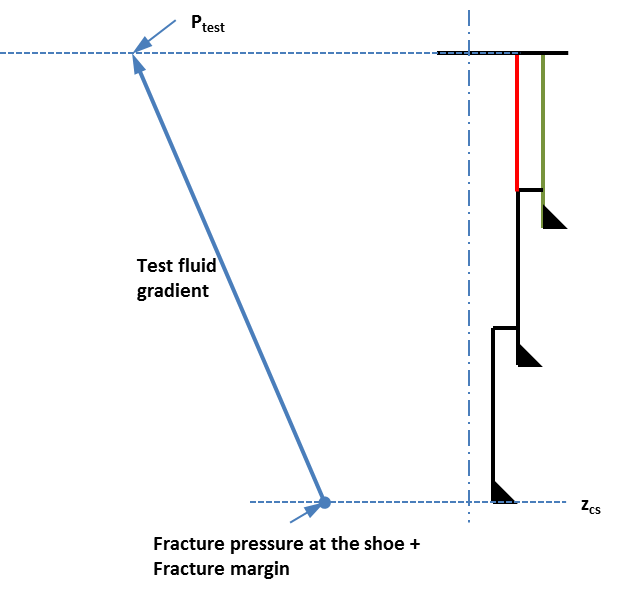
¶ CIT methodology
This pressure test assumes fracture pressure (anticipated leak off pressure with a margin) at the shoe of the current string. The test pressure is calculated as following - ptest = C[ρleakoff(zcs) + ρmargin − ρi]zcs
where,
- zcs = true vertical depth of the current shoe, ft
- ρleakoff = fracture (or leakoff) density at the current shoe depth, ppg
- ρmargin = fracture density margin, ppg. The default fracture margin is 0.5 ppg
- ρi = test fluid density, ppg
This load simulates required pressure test for drilling liners according to BSEE (eCFE §250.721(b)) and discussed in the next section.
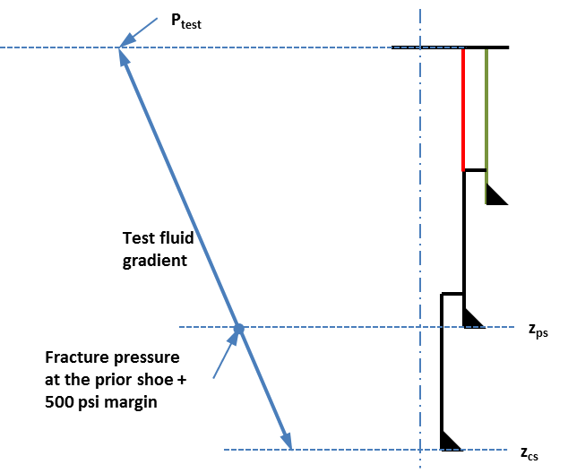
¶ Production Liner Pressure (BSEE) methodology
This pressure test assumes fracture pressure (anticipated leak off pressure with a margin) at the prior string shoe. The test pressure is calculated as following - ptest = [pFG(zps) + pFGmargin] − Cρizps
where,
- zps = true vertical depth of the prior shoe, ft
- pFG(zps) = fracture pressure at the prior shoe depth, psi
- pFGmargin = fracture pressure margin, psi. Default fracture pressure margin is 500 psi
- ρi = test fluid density, ppg
This load simulates required pressure test for production liners according to BSEE (eCFE §250.721(c)) and discussed in the next section.
¶ Specify Surface Pressure methodology
Internal pressure profile is constructed with the test pressure on top the internal (test) fluid hydrostatic pi(z) = ptest + Cρiz
¶ Comments on BSEE’s eCFR
- For conductor casing, the external pressure should use seawater density.
- According to eCFE §250.721(a), the pressure test for full string (non-liner) is following -
- Drive or structural casing: Not required
- Conductor casing: 250 psi
- Surface, intermediate, drilling, and production casing and tieback: 70% of MIYP
- According to eCFR, the minimum test pressure is suggested as the 70% of the string’s minimum internal yield. Following equation may have been suggested in contrast to what is stated earlier – ptest = 0.7PAPI MIYP This does not consider the effective load (internal pressure minus external pressure) on the string rather only the API burst strength of the string.
For drilling liner eCFE §250.721(b) -
- Each drilling liner and liner-top to a pressure at least equal to the anticipated leak-off pressure of the formation below that liner shoe, or subsequent liner shoes if set. Following equation will be used to calculate FIT pressure5 - pFIT = [FG(zshoe) + FGmargin]Czshoe ptest = pFIT − Cρizshoe where,
- zshoe = shoe depth of the current liner or the deepest subsequent liner shoe, ft TVD
- FG(zshoe) = fracture gradient at zshoe, ppg
- FGmargin = fracture margin, ppg. The default fracture margin is 0.5 ppg.
- For production liner eCFE §250.721(c) -
- Each production liner and liner-top to a minimum of 500 psi above the formation fracture pressure at the casing (or previous liner) shoe into which the liner is lapped. The test pressure for the production liner will be calculated using the following equation - ptest − prod liner = [PFG(zps) + 500] − Cρizps
- For a produced well eCFE §250.721(e) -
- For a well that is fully cased and cemented, pressure test the entire well to maximum anticipated shut-in tubing pressure, not to exceed 70% of the burst rating limit of the weakest component before perforating the casing or liner, or
- For an open-hole completion, pressure test the entire well to maximum anticipated shut-in tubing pressure, not to exceed 70% of the burst rating limit of the weakest component before you drill the open-hole section.
¶ Pressure Test with a Plug
- Add a plug for options "(I) Fraction of MIYP" and "(IV) Specify Surface Pressure". The plug depth is equal or shallower than the string shoe depth. There will be no ptest below the plug depth. Therefore, there will be a pressure discontinuity at the plug depth. The internal pressure below the plug depth will be calculated as - pi(z) = Cρiz