¶ Packer Leak
Packer leak can occur during Early or late life production. During early life, hydrostatic pressure of the production fluid at the bottom of the packer may go lower than the hydrostatic pressure of the packer fluid above the packer. During that time if we assume packer leak then packer fluid will drop, leak through the packer seal, mix with the production fluid and will flow through the production tubing. As production continues, the formation pressure keeps declining.
During late life of the well, formation pressure goes such a lower value that the well is getting ready to be abandoned. Packer leak during late life production that is close to abandonment is more severe than early life packer leak. This is because, the packer fluid column will drop much deeper. In fact, at the lowest formation pressure, due to much higher packer fluid, the well may have been killed unless the rate of the leak is very slow. The internal and external pressure profiles for both types of packer leak are discussed in this section.
¶ Internal Pressure
Black lines are the internal pressure profiles for a casing, a liner and a tieback. Internal pressure calculation starts at point 4 and is equal to the pore pressure at the perforation depth. The line 1-7-6-4-5 and and the line 1-2-3-4-5 are the internal pressure profiles for the early and late life packer leak respectively.
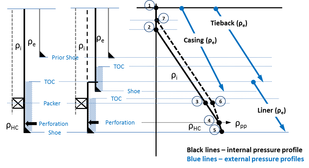
Following are the depths of interest in developing the internal pressure profile -
Point 4 - Perforation depth.
Entered as MD and will be converted to TVD. It is defaulted to the shoe of the deepest production string. Perforation depth can not be deeper than the shoe of the deepest production string and shallower than the production packer.
Pressure at the perforation depth is defaulted to the pore pressure at the perforation depth.
Point 6 and Point 3 - Packer depth.
Pressure below the packer is calculated using (1) hydrocarbon fluid density in early life packer leak which will lead Point 4 to Point 6 or (2) packer fluid density in late life packer leak which will lead Point 4 to Point 3.
Point 7 and Point 2 - Packer fluid column drop depth.
Packer fluid column drop varies because of the pressure at the base of the packer fluid pressures at the Point 6 and Point 3. It is also important to note that, at least Point 7 if not Point 2 may have been above the mudline, there will be a non zero pressure at the mudline casing hanger.
Following are the description of how to construct the internal pressure profile -
Internal pressure for the early life packer leak, the line 1-7-6-4-5 can be constructed as following -
Point 4 at z = zperf - equal to the pore pressure at the perforation depth pi(zperf) = ppp(zperf)
Between Point 4 and Point 6 - pressure at the perforation depth minus the hydrostatic pressure with hydrocarbon fluid density. pi(z) = pi(zperf) − Cρhc(zperf−z)
Point 6 pressure at the packer, z = zpacker - pi(zpacker) = pi(zperf) − Cρhc(zperf−zpacker)
Between Point 6 and Point 7 - pressure at the packer minus hydrostatic pressure with the packer (internal) fluid density. pi(z) = pi(zpacker) − Cρi(zpacker−z)
Pressure at Point 7 should be zero. In fact packer fluid drops to Point 7 from Point 1. Packer fluid column drop can be calculated as following from the earlier equation by entering zero in the left hand side and making z = z7 - $$z_{_{7}}= z_{_{packer}} - \left[\cfrac{p_i(z_{_{packer}})}{C\times \rho_{_{i}}} \right]$$
Between Point 4 and Point 5, pressure is calculated using hydrocarbon fluid density as following - pi(z) = pi(zperf) + Cρhc(z−zperf)
Point 5, pressure at the shoe, z = zcs - pi(z) = pi(zperf) + Cρhc(zcs−zperf)
where,
C = conversion factor, 0.051948 psi/(ppg×ft)
ρhc = hydrocarbon fluid density, ppg
ρi = packer (internal) fluid density, ppg
z = true vertical depth of interest, ft
z7 = true vertical depth of the fluid column drop, ft (pi(z7) = 0)
zcs = true vertical depth of the current shoe, ft
zperf = true vertical depth of the perforation, ft
zpacker = true vertical depth of the packer, ft
pi(z) = internal pressure at depth z, psi
pi(zperf) = internal pressure at the perforation depth, psi
ppp(zperf) = pore pressure at the perforation depth, psi
pi(zpacker) = internal pressure at the packer depth, psi
Internal pressure for the late life packer leak, the line 1-7-6-4-5 can be constructed as following -
Point 4 at z = zperf - equal to the pore pressure at the perforation depth pi(zperf) = ppp(zperf)
Between Point 4 and Point 3 - pressure at the perforation depth minus the hydrostatic pressure with packer (internal) fluid density. pi(z) = pi(zperf) − Cρi(zperf−z)
Point 3 pressure at the packer, z = zpacker - pi(zpacker) = pi(zperf) − Cρi(zperf−zpacker)
Between Point 3 and Point 2 - pressure at the packer minus hydrostatic pressure with the packer (internal) fluid density. pi(z) = pi(zpacker) − Cρi(zpacker−z)
Pressure at Point 2 should be zero. In fact packer fluid drops to Point 2 from Point 1. Packer fluid column drop can be calculated as following from the earlier equation by entering zero in the left hand side and making z = z2 - $$z_{_{2}}= z_{_{packer}} - \left[\cfrac{p_i(z_{_{packer}})}{C\times \rho_{_{i}}} \right]$$
Between Point 4 and Point 5, pressure is calculated using hydrocarbon fluid density as following - pi(z) = pi(zperf) + Cρhc(z−zperf)
Point 5, pressure at the shoe, z = zcs - pi(z) = pi(zperf) + Cρhc(zcs−zperf)
where,
z2 = true vertical depth of the fluid column drop, ft (pi(z2) = 0)
In summary, the internal pressure profiles for the early and late life packer leaks can be differentiated by how we reach Point 6 (early life packer leak) and Point 3 (late life packer leak). This could be done by having radio buttons for each of these two options.
¶ External Pressure
Default external pressure is assumed according to Blade’s External Pressure Protocol for collapse load. It is described as following -
Trapped hydrostatic with original mud density from the hanger to the shoe for the strings drilled with riser. For the strings drilled without riser, the pressure at the mudline is calculated as seawater hydrostatic and then original mud density to the shoe.
At the hanger, at z = zh for strings drilled with riser pe(zh) = Cρomzh Pressure at the top of the liner at zh = zTOL pe(zh) = CρomzTOL
At the hanger, at z = zh = zML for strings drilled without riser (conductor and surface casings). Packer leak load is associated with production strings and they are installed with riser. Therefore following equation will not be used in this load case. pe(zh) = CρswzWD
Between hanger to the shoe, at zh ≤ z ≤ zcs pe(z) = pe(zh) + Cρom(z−zh)
where,
ρom = original mud density, ppg
ρsw = seawater density (8.66), ppg
zh = true vertical depth of the hanger, ft
zTOL = true vertical depth of the top of the liner, ft
zML = mudline depth, ft
zWD = seawater depth, ft
pe(z) = external pressure at depth z, psi
pe(zh) = external pressure at the string hanger, psi
Blue lines are the external pressure profiles for a casing, a liner and a tieback. Production string sections are drilled with riser. Therefore, the second equation is not valid for this load case.
For non conservative but realistic at least for the late life packer leak, user may choose mud-base fluid density instead of original mud below the hanger.
¶ Production Tubing
The internal pressure for the production string discussed earlier in this section will be the external pressure for the production tubing. The internal pressure profile for production tubing can simply be generated using the following equation - pi(z) = pi(zperf) − Cρhc(zperf−z)
¶ Temperature
Undisturbed temperature is assumed as default temperature profile. Late life production temperature profile could also be a choice. All thermal loads and user defined temperature profiles are therefore available for this load case.