¶ Negative Pressure Test
- Negative pressure test load is required for all strings except for the conductor drive pipe and tubing.
- It is a post installation collapse load.
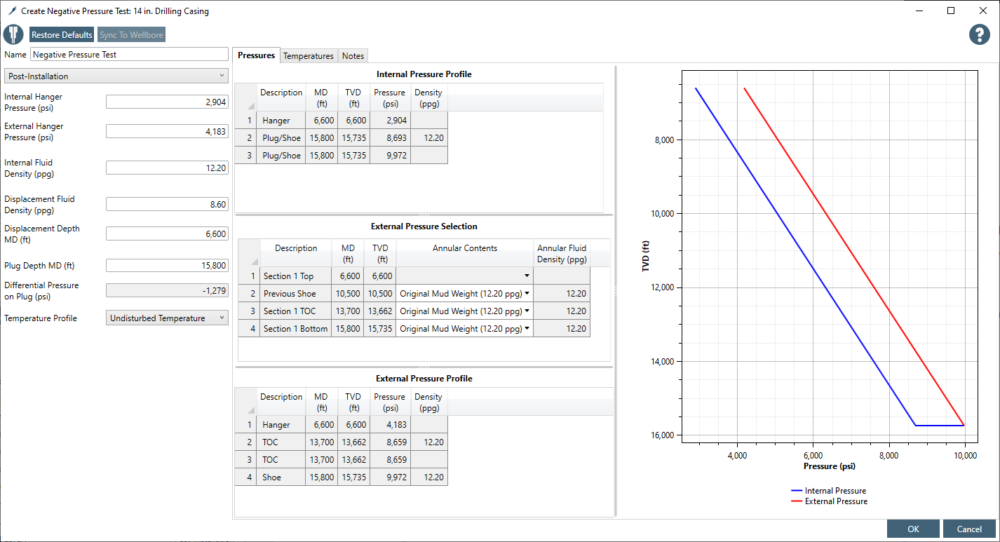
- INPUTS and Immediate OUTPUTs in the form
- Displacement fluid depth. Default depth will be (1) mudline for offshore subsea wells or (2) 200 ft for other wells and (3) will not be deeper than the plug depth.
- Displacement fluid density. Default density will be seawater density (8.6 ppg). Displacement fluid density should be equal to or less than the internal fluid density. For higher fluid density (application will accept) this load may not reflect negative pressure test as expected. User will be cautious about that.
- Calculate and show the pressure at the displacement fluid depth.
- Plug depth. Default depth will be the string shoe. Plug depth can not be deeper than the string shoe or shallower than the string top or shallower than the displacement fluid depth.
- Internal fluid density. Default density will be the internal fluid density (from casing program).
- Calculate and show (if possible, not a must) the pressures at the top ppt and base ppb of the plug.
- Calculate and show the differential pressure Δp across the plug.
- External fluid density. Default density will be the external fluid densities (from casing program).
- The external pressure input table should look like the same as other standard loads. It should have all default depths as usual.
- Calculate and show the pressure at the top of the string and make this pressure editable. Since the external pressure protocol uses top-down calculation, this pressure will be the starting point for the external pressure profile.

¶ Internal pressure profile
Internal pressure at the -
- displacement fluid depth (default at mudline for offshore subsea wells or at 200 ft for other wells) - pi(zdf) = Cρdfzdf
- Internal pressure above the displacement fluid depth - pi(z) = pi(zdf) − Cρdf(zdf−z)
- Internal pressure below the displacement fluid depth to the plug depth - pi(z) = pi(zdf) + Cρi(z−zdf)
- Internal pressure at the liner top where displacement fluid depth is shallower than the liner top depth - pi(zTOL) = pi(zdf) + Cρi(zTOL−zdf)
- Internal pressure at the liner top where displacement fluid depth is deeper than the liner top depth - pi(zTOL) = CρdfzTOL
- Internal pressure at the top of the plug depth - ppt = pi(zdf) + Cρi(zpt−zdf)
Internal pressure below the plug -
- First calculate pressure at the base of the string pcs = pi(zcs) = Cρizcs This pressure may or may not be equal to the external pressure at this depth.
- Then calculate pressure from the base of the string to the bottom of the plug pi(z) = pcs − Cρi(zcs−z) Internal pressure at the base of the plug depth - ppb = pi(zcs) − Cρi(zcs−zpb) For the case where the plug is at the shoe depth, ppb = pcs. This may or may not be equal to the external pressure at this depth.
The pressure difference between the top of the plug and the base of the plug will be negative. Δp = ppt − ppb
where,
- C = density to pressure conversion factor (0.051948 psi/ppg-ft)
- pi(z) = internal pressure at the depth of interest, psi
- ppt = internal pressure at the top of the plug, psi
- ppb = internal pressure at the base of the plug, psi
- ρi = original fluid density inside of the string, ppg
- ρdf = displacement fluid density, ppg.
- ρsw = seawater density, ppg. Default density of 8.6 ppg is assumed.
- z = true vertical depth of interest, ft
- zdf = displacement fluid depth, ft TVD
- zpt = true vertical depth of the top of the plug, ft
- zpb = true vertical depth of the base of the plug, ft
- zcs = true vertical depth of the bottom of the string, ft
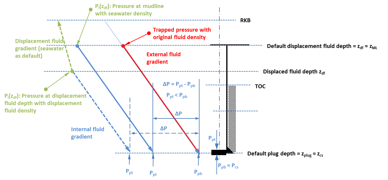
Internal (blue and green) and external (red) pressure profiles internal (blue and green) and external (red) pressure profiles for the negative pressure test when the plug is at the shoe depth.
Solid blue line shows the internal pressure profile where the default displacement fluid depth is at the mudline with seawater as displacement fluid. The dashed blue and green lines show the internal pressure profile where the displacement fluid depth is deeper than the mudline.
By displacing more depth with lighter fluid than internal fluid density, the internal pressure at the top of the plug will be lower than the base case which will make the negative differential pressure Δp across the plug.

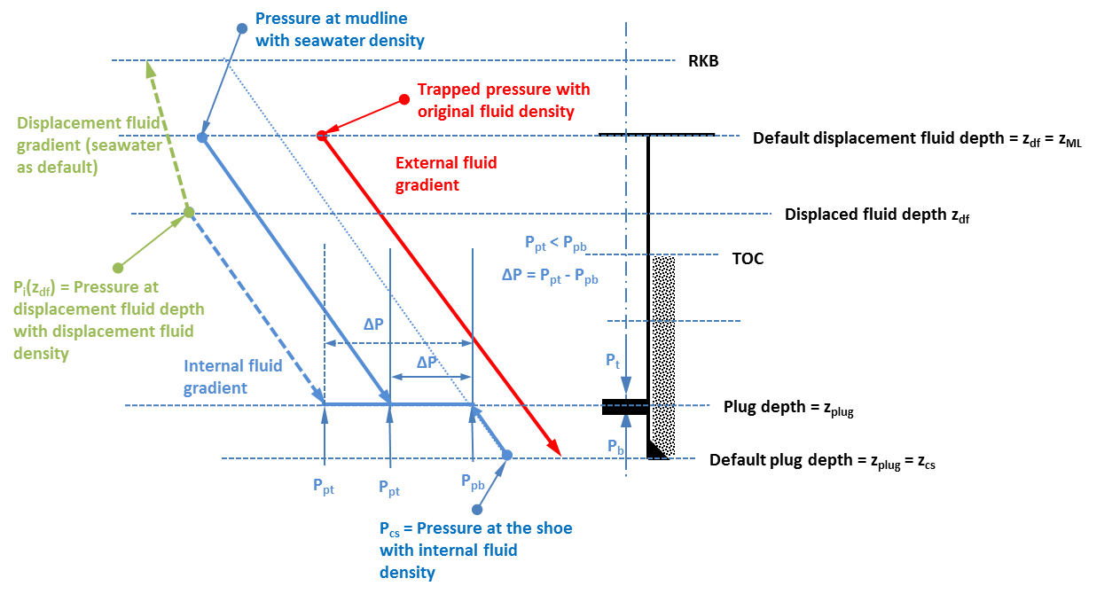
The above logic in calculating internal pressure will also be valid for a liner.

¶ External pressure profile
The solid red lines in the first and second images shows the external pressure profile for this load case by Blade External Pressure protocol. The summary of the external pressure profile is as following -
- external pressure for casing and tieback -
- pressure at the hanger (top of the string)
- Pe(ztop) = CpezML - for conductor and surface casings of offshore subsea wells
- Pe(ztop) = CpswzWD - for all other strings of offshore subsea wells
- Pe(ztop) = 0 - for all strings of offshore platform and onshore wells
- pressure from top to the bottom of the string pe(z) = pe(ztop) + Cρe(z−ztop)
- pressure at the hanger (top of the string)
- external pressure for liner - pe(z) = Cρez
- external pressure for tubing
- pressure from the top of the tubing to packer pe(z) = Cρpackerz
- from packer to end of tubing pe(z) = Cρiz
where,
- pe(ztop) = external pressure at the top of the string, psi
- pe(z) = external pressure at the depth of interest, psi
- ρe = original fluid density outside of the string, ppg
- ρpacker = packer fluid density, ppg
- ztop = true vertical depth of the top of the string, ft
¶ Temperature profile
Undisturbed temperature profile is assumed as default.
¶ Negative pressure testing requirement according to BSEE
- (eCFE §250.721(b)) You must perform a negative pressure test on all wells that use a subsea BOP stack or wells with mudline suspension systems.
- You must perform a negative pressure test on your final casing string or liner. This test must be conducted after setting your second barrier just above the shoe track, but prior to conducting any completion operations.
- You must perform a negative pressure test prior to unlatching the BOP at any point in the well. The negative pressure test must be performed on those components, at a minimum, that will be exposed to the negative differential pressure that will occur when the BOP is disconnected.
- The District Manager may require you to perform additional negative pressure tests on other casing strings or liners (e.g., intermediate casing string or liner) or on wells with a surface BOP stack as appropriate to demonstrate casing or liner integrity.
- You must submit for approval with your APD or APM, test procedures and criteria for a successful negative pressure test. If any of your test procedures or criteria for a successful test change, you must submit for approval the changes in a revised APD or APM.
- You must document all your test results and make them available to BSEE upon request.
- If you have any indication of a failed negative pressure test, such as, but not limited to, pressure buildup or observed flow, you must immediately investigate the cause. If your investigation confirms that a failure occurred during the negative pressure test, you must:
- Correct the problem and immediately notify the appropriate District Manager; and
- Submit a description of the corrective action taken and receive approval from the appropriate District Manager for the retest.
- You must have two barriers in place, as described in §250.420(b)(3), at any time and for any well, prior to performing the negative pressure test.
- You must include documentation of the successful negative pressure test in the End-of-Operations Report (Form BSEE-0125).
- No predefined negative set pressure for this testing is stated in the above code.