¶ Initial Condition
The Initial Condition load case describes the physical condition that the tubular is in, just before the cement gets dry, the cement is still wet.
In its most common form, the Initial Condition load case is the "as cemented" state for a string. Therefore, it is usually, though not necessarily, the Installation load for a string. Initial condition is required for all string categories to create post installation load cases. Wet cement is used as external fluid density except for production tubing where the tubing is not cemented. Packer fluid instead of cement density is used in production tubing.
¶ Internal pressure profile
Internal pressure assumes run-in fluid density from the string top to the string bottom as default. Fluid density of the subsequent hole section to be drilled can also be used if it is run behind the cement column. For production tubing, the packer fluid is assumed.
For subsea surface and conductor casings pi(z) = pti + Cρi(z−zRKB)
For all other strings of the subsea wells and all strings for the onshore and platform wells pi(z) = pti + Cρiz
where
C = conversion factor, 0.051948 psi/(ppg×ft)
pi(z) = internal pressure at the depth of interest, psi
pti = internal pressure applied at the top of the string, psi. Default value is zero. It is not explicitly entered in the program, but can be added on top of the default pressure at the hanger depth.
ρi = internal fluid density, ppg
z = true vertical depth of the interest, ft
zRKB = RKB elevation depth, ft
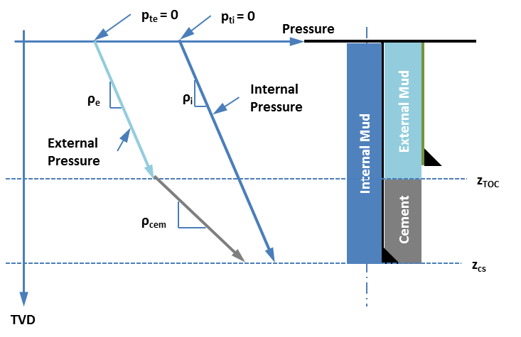
¶ External pressure profile
External pressure assumes run in fluid density from the string top to the TOC and cement density below the TOC to the string bottom. In case for the tubing, it is the packer fluid from the top of the tubing to the packer depth and then internal fluid density from the packer depth to the end of tubing.
External pressure at the top of the string -
The general equation of the external pressure at the top of the string - pe(ztop) = pte + C × ρe × (ztop−zRKB) where,
C = conversion factor, 0.051948 psi/(ppg×ft)
ρe = external fluid density which is the running fluid density for the string of interest.
pte = external pressure applied at the top of the annulus, psi. Default value is zero. It is not explicitly entered in the program, but can be added on top of the default pressure at the hanger depth.
For offshore subsea casings drilled without riser (currently we are assuming conductor and surface casings are drilled without riser), the pressure at the mudline is - pe(zML) = pte + C × ρsw × (zML−zRKB) where, (zML−zRKB) is equal to water depth and ρsw is seawater density (8.6 ppg as default).
Pressure at the top of the liner in all offshore well types - pe(zTOL) = pe(zML) + C × ρe × (zTOL−zML) pe(zTOL) = pe(zRKB) + C × ρe × (zML−zRKB) + C × ρe × (zTOL−zML)
For onshore and offshore platform wells, the pressure at the top of the string is equal to the applied pressure (if any) in the annulus which is defaulted to zero. pe(ztop) = pte
External pressure from the top of the annulus to the TOC (ztop ≤ z ≤ zTOC) - pe(z) = pe(ztop) + C × ρe × (z−ztop) External pressure at the top of the (lead) cement - pe(zTOC) = pe(ztop) + C × ρe × (zTOC−ztop)
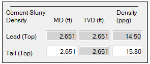
Pressure from the top of the (lead) cement to top of the tail slurry depth zTOC < z ≤ ztail top - pe(z) = pe(zTOC) + C × ρlead × (z−zTOC) Pressure at the top of the tail slurry depth - pztail top = pzTOC + C × ρlead × (ztail top−zTOC) Pressure from the top of tail slurry to the current shoe depth ztail top < z ≤ zshoe - pe(z) = pztail top + C × ρtail × (z−ztail top) External pressure at the shoe - pe(zshoe) = pztail top + C × ρtail × (zshoe−ztail top) where,
ρlead = lead cement density, ppg
ρtail = tail cement density, ppg
zshoe = true vertical depth of the shoe, ft
ztail top = true vertical depth of the top of the tail, ft
zTOC = true vertical depth of the (lead) cement, ft
¶ Temperature profile
Undisturbed temperature is assumed as the default temperature profile.
The Initial Condition load case describes the physical condition that the tubular is in, just prior to the application of any other load conditions. In its most common form, the Initial Condition load case is the ’as cemented’ state for a string of casing or a liner. Therefore it is usually, though not necessarily, the Installation load for a string.
¶ Inputs
This load case utilizes the Undisturbed Temperature Profile.
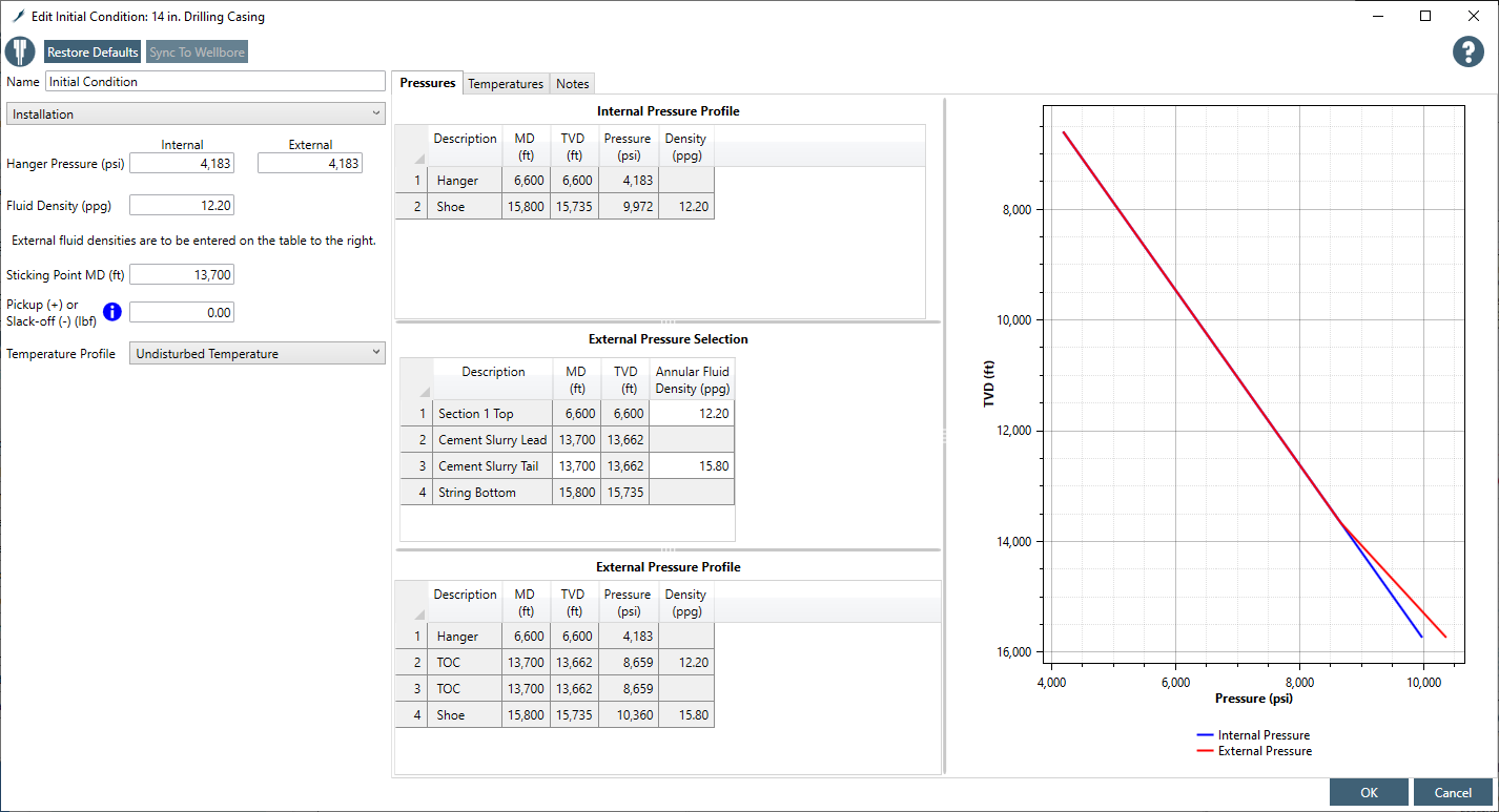
The inputs include:
Description
Pressure at Hanger (Inside)
Pressure at Hanger (Outside)
Fluid Density Inside the Casing
Sticking Point
Pickup (+) or Slack-off (-)
Cement Slurry Density & Depth Matrix
The Sticking Point and Pickup/Slackoff inputs allow the well designer to specify any pre-tension or set-down load that is applied to the uncemented portion of a string as part of its Initial Condition.
The Description is nothing more than the load’s name, which can be edited by the well designer.
The Pressure at Hanger (Inside) is the hydrostatic pressure of the fluid inside the casing at the wellhead. The default value is the pressure resulting from the mud density in which the string was run. While this field can be edited, it will rarely need to be.
The Pressure at Hanger (Outside) is the hydrostatic pressure of the annulus fluid outside the casing at the wellhead. The default value is the pressure resulting from the mud density in which the string was run. While this field can be edited, it will rarely need to be.
The Fluid Density Inside the Casing is just as it sounds, the density of the fluid inside the casing. The most common fluid density will be that of the displacement fluid used while cementing the casing. This is the default.
The Cement Slurry Density & Depth Matrix is a small table that defines the hydrostatic components of the cement-filled portion of the subject string’s annulus. If the well designer enters a depth for the Top of Tail Slurry that is below the top of Cement (TOC), StrinGnosis® will activate the data input field for Density of the Lead Slurry. The well designer can also specify the density of the Tail Slurry.